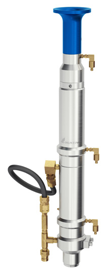
Cleanline Grease Injection Control Head - DLW (Dual Line Wiper)

Features
Benefits
  • • Dual Linewipers – can be operated independently, with single return line, or simultaneously , with two independent return lines
    • Easy to add additional flow tubes
    • Grease injection ball safety feature
  • • Having two Linewipers reduces downtime between pump –down jobs to service rubbers.
    • The dual line wipers can each have their own return line to use both line wipers at the same time. This places less stripping stress on each Linewiper rubber and extends further the time between rubber change-out.
    • Additional flow tubes can be added for gas well operations
    • Velocity ball prevents the escape of well fluids should the grease injection line connection fail
     

Features

• Dual Linewipers – can be operated independently, with single return line, or simultaneously , with two independent return lines
• Easy to add additional flow tubes
• Grease injection ball safety feature

Benefits

• Having two Linewipers reduces downtime between pump –down jobs to service rubbers.
• The dual line wipers can each have their own return line to use both line wipers at the same time. This places less stripping stress on each Linewiper rubber and extends further the time between rubber change-out.
• Additional flow tubes can be added for gas well operations
• Velocity ball prevents the escape of well fluids should the grease injection line connection fail
 

Hunting grease injection control heads are designed to contain well pressure whilst running braided line or electric line cable operations.

Grease injection control heads are made up of two main assemblies; the Pack off / Linewiper assembly and the flow tube assembly.

The pack off assembly provides sealing capability when the wireline is stationary.

The line wiper is energised to clean the cable when pulling out of the well. The Hunting Cleanline system incorporates integral line wipers with a protective check valve between the Linewiper assemblies, eliminating the requirement for a separate second drain hose for the line wiper.

The flow tube assembly is made up of a number of close tolerance flow tubes that are sized to the diameter of the wireline / cable being used. Grease is then pumped into the annular void between the flow tube and the cable creating a pressure drop across each flowtube.

The number of flow tubes required is dependent on expected well pressures and well fluids.

An additional flowtube injection assembly can be added to provide more grease volume

An inline Vent Valve can be installed below the bottom flowtube. Its use reduces the risk of adiabatic heating cable damage during wellsite pressure testing.

Product Image 1